


There’s an old saying, it’s always easier to take something apart than it is to put it back together. This, for sure, is the case with engines, but there are lots of things an engine can tell you when you conduct engine repairs or disassemble it for rebuild. Your first order of business is to have a shop manual, don’t even attempt to do this job without one. If you decide to upgrade your car’s engine, you may consider putting in a 6.0 powerstroke engine. Consult with an auto engine repair technician if you’re unsure how to fix or upgrade your engine.
Getting that lump of iron on the engine stand
First off, let’s get the engine on the engine stand, sounds easy enough, right, but there are a few hurdles to jump here. Most universal engine stand adapters mount to the rear side of the block, and you will need to remove the clutch, flywheel, and engine back plate before you can mount the engine to the adapter, otherwise you would not be able to remove the crankshaft once it’s on the engine stand. The next thing to make sure you have is the correct bolts in the proper lengths needed to mount the adapter to the back of the engine block. If you are new to British engines, you’ll immediately find out they use mostly SAE fine thread bolts and nuts, not always easy to find at your chain home improvement stores, so a well stocked local hardware store, or fastener specialty store will be your best place to find the right bolts.
Cylinder head, pushrods and tappets
Ok, let’s get started with the actual disassembly of the engine. I tell people all the time the proper sequence will make this job a lot easier, both in disassembly and assembly. A good place to start is removing the cylinder head.
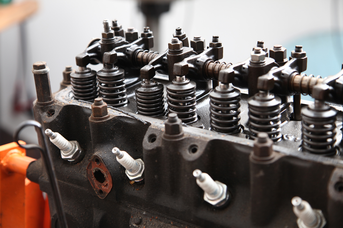
Remove all the cylinder head stud nuts first and save the arm pedestal stud bolts for last.What you are doing is using the rocker arm assembly, which will have some valves open at the time, to help break the seal of the head from the block. Once the head is loose, but not removed, it is time to remove the rocker arm assembly.
Now that the rocker arm assembly is off you can remove the push rods.
Inspect: The pushrods to be sure they are not bent and the tips are not worn. If your pushrods look good and you plan on reusing them, organize them in the order they came out.

Pushrods showing signs of wear and need replacing

Removing pushrods before removing the cylinder head

Open valves aid in separating the head from the block.
Remove the cylinder head from the block and start removing the cylinder head studs. This can be done by taking two of the head stud nuts, threading them
onto a stud and tightening them against each other, and then turning the lower of the two nuts to loosen the studs. Or, you can buy an inexpensive set of stud sockets to make this job quicker, and easier.
Inspect: I always replace the head studs but if you want to reuse yours, you must look for stretched studs. Damaged head studs will need to be replaced.

Removing cylinder head

Stretched head stud needs replacing

Using double-nut method to remove head studs.
Remove the tappets (lifters). Some engines have a tappet cover, if so, remove it to access the lifters. If your engine doesn’t have a tappet cover then you will remove them by one of several methods depending on the engine. For example with Triumph you simply reach into the block and remove them. On a 1275 engine, the cam will have to be removed before you can remove the lifters.
Inspect: The tappets for any pitting on the surface that contacts the camshaft. This is a sure sign they need replacing.
If you plan on reusing your tappets you must keep them in the exact order they came out. Each cam lobe and lifter will have its own unique wear pattern to each other, and if you don’t maintain this order, then you can’t reuse the lifters. In most cases these engines are 30, 40, 50 years old, and will probably need new lifters and a new camshaft anyway, but for now keep the order correct until you know that for sure.

Worn and pitted tappet on left requires replacing along with the camshaft

Pulling tappet up and out of its hole

Removing the tappets through the side cover
Stripping the front of the motor
Remove the crankshaft pulley nut and pulley. The best way to remove the crankshaft pulley nut is with an impact wrench, either air or electric. If you don’t have access to an impact wrench, then you’ll need a long handle breaker bar and a piece of wood to wedge the crankshaft with.
Remove the front crankshaft pulley/balancer with a special puller kit, but two long screwdrivers, or pry bars, used carefully will do the trick as well, and this is how I’ve always done it.
Inspect: The crank pulley for any cracking of the rubber damper between the inner and outer pulley. If the rubber is bad you will need to have the pulley rebuilt or buy a new one.
Remove the timing cover, the timing chain and gears, timing chain tensioner (on some engines), the cam thrust plate, then the front engine plate. Now is also the time to remove the water pump, pulleys and oil pan.
Inspect: The cam thrust plate for any signs of wear and replace as necessary. I always replace the timing chain, gears, tensioner and water pump at a minimum. These parts are readily available and inexpensive enough that it isn’t worth taking a chance on using old parts. If there is a double row timing chain upgrade available for your car then go with that.

Removing cam gear retaining bolt

Remove and inspect the cam retaining plate

Removing cam gear and chain
Oil pump
We are down to the engine block assembly. Start by inverting the engine block.
Remove the oil pump and oil pump drive gear, most of our engines will have the oil pump here, there are a few exceptions, like the MOWOG A-Series engines found in the MG Midgets, Austin Healey Sprites, and Morris Minors, to name a few, which drive the oil pump off the back of the camshaft.
Inspect: I always replace the oil pump. Inspect the pick-up screen and if damaged, replace it as well.

Removing oil pump drive gear

Removing oil pump mounting bolts. Notice damaged strainer

Removing oil pump body
Connecting rods and pistons
Remove the connecting rods and pistons. Make sure you keep the order of these as well, some engines like the MOWOG A-Series engines will have the connecting rod order numbers stamped on them, others like the MGB will not, so you may need to mark them as they come out. Start by removing the connecting rod bolts, or nuts, and separating the rod cap from the connecting rod, now you can push the connecting rod and piston out thru the top side of the block (a rubber hammer handle works well for this). Make sure to keep one hand at the top of the block to catch the piston and connecting rod as it comes out of the cylinder, so they don’t fall to the ground and get damaged.
Inspect: I always replace rod bearings and rod bolts. The cylinders need to be checked by a machine shop for wear and roundness to see if the engine block needs boring. Most of my engine rebuilds require a bore job. Your machine shop will be able to determine if the block needs boring and what oversize pistons you will need.

Forcing rod and piston from engine. Be sure to catch it.

Removing connect rod nuts

Removing connecting rod bearing cap
Crankshaft
Before removing the crankshaft main bolts and caps you will want to measure the end float so you have an idea of the amount of wear on the thrust bearings. This is where your shop manual will come in handy. In some engines, like the MOWOG A-Series engine, they hardly ever wear the thrust bearings out of spec. If in spec, then you can clean them and retain them for assembly later. On some engines like the Spitfire and TR6 they can heavily wear the thrust bearings and this will tell you how much wear has occurred and that info may help you to order the needed oversized thrust washers.
Remove the crankshaft main bolts and caps in preparation to remove the crankshaft. Some engines have what is often times referred to as “saddled” main caps, this type will be extremely hard to remove by hand. The MG B-Series engine (MGA, MGB, Magnette, etc.) have this type of main cap and you’ll find these engines have thread holes in the main caps. I use a slide hammer with simple adapters I have made over the years, as an example, by using a nut the size of the end threads of the slide hammer, and a bolt the size I need welded together—makes for a simple but effective bearing cap removal tool. One of your main caps will have the thrust bearings housed with it as well—normally the center main cap on MG engines and the back main cap on Triumph engines. Once all main caps are removed then pull out the crankshaft and main bearings.
Inspect: I always replace main bearings. Have your machine shop inspect your crankshaft and see if it needs grinding undersize. You will also want to have the crankshaft crack checked. Don’t disregard measuring the crankshaft because the journals visually look fine. It needs to be measured. A crankshaft’s journals can look good and still be under spec. The machinist can also check the alignment of the main bore for the crankshaft in the block. You seldom have to line bore a block but you still want to have it checked.

Removing main bearing cap
Measuring thrust bearing clearance prior to disassembly

Removing main bearing cap bolts

Main bearing showing wear.

Removing thrust bearings
Camshaft and Distributor
Remove the distributor, distributor plate on the block, and the distributor drive gear. The camshaft will not come out of the block until the distributor drive gear has been removed. On many of our engines the distributor drive gears will have a threaded hole in the center. You can use a long bolt with the proper size and thread to thread into the hole in the distributor drive gear to remove it. Now remove the camshaft by exiting it towards the front of the engine block. On most engines the rear camshaft journal will be smaller in size than the other camshaft journals, so this is the only direction from which you can remove the camshaft. Be careful when doing this as to not let the lobes and gear of the camshaft scratch the cam bearings. In some cases you may be able to rebuild your engine without replacing the camshaft bearings, although I recommend replacing them. Some of our engines may not even have cam bearings, for example the Triumph/MG Midget 1500, however you still need to take great care in removing the camshaft from the block. The removal and installation of cam bearings will require special tools.
Inspect: Your camshaft by carefully looking at the lobes. If you see worn or flat lobes then it will need to be replaced. I always replace cam bearings.

Removing distributor base plate

Removing distributor drive gear

Removing the camshaft

Notice the 1st & 2nd lobes are worn and flat compared to the 3rd. Cam needs replacing.
Oil pressure regulator
We are getting close to having a bare block, but there is still more to do.
Remove the oil pressure regulator assembly—first the cap bolt, then the spring, and the piston/plunger, or cup. In the case of the cup found in many of the MG engines, a small magnet on a handle will come in handy if it does not come out with the spring. Make sure you get all the removable components of the oil pressure regulator out of the engine block.
Inspect: I always replace the oil pressure spring and plunger/cup.

Removing oil pressure spring cap

Removing oil pressure spring and plunger
Various threaded plugs and fitting
Remove the threaded plugs, fittings, and oil fittings on the block. Be sure to retain all of these, even the hex head plugs, as many of them have unique British threads.
Inspect: Most, if not all, of these plugs can be reused as long as the threads and heads are in good shape.

Removing various threaded plugs

Hex head threaded plug
Oil galley plugs
Let’s talk about what brass plugs need to be removed from your block and what brass plugs do not. Some brass plugs in your block are not oil galley plugs at all, but were used for plugging various holes drilled into the block during manufacturing for another purpose. You will need to study your block and identify which are oil galley plugs and which are not and only remove the oil galley plugs. Now one might ask why do I need to remove the oil galley plugs in the first place? The answer is simple. A lot of gunked up oil can be in these oil galley passages and the only way to properly clean this area is to remove the plugs.
Remove brass oil galley plugs. I drill them in preparation to tap them ¼”-20, then I have a ¼”-20 bolt adapter for my slide hammer. I screw the adapter into the drilled and tapped hole in the brass oil galley plug and then simply slide hammer it out. Trying to drill them out could damage the roundness of the hole and now normal replacement plug now may not work.
Inspect: There’s nothing to inspect. Just buy new plugs to replace the ones you removed.

Removing oil galley plug

Drilling oil galley plug for tapping

Tapping oil galley plug for removal
Freeze plugs
There really isn’t anything to removing freeze plugs. You can easily do this yourself.
Remove: Use a hammer and sharp edged chisel, make a slit with the chisel in the middle of the freeze plug and then simply pluck it out of the block with a screwdriver.
Inspect: There’s nothing to inspect. Just buy new plugs to replace the ones you removed.

Slitting core plugs for removal

Removing core plug with screw driver
It’s all apart, now what
Now you need to figure out what parts need to be replaced. Some parts are a given like gaskets, seals and the parts I called out in the previous pages. Other parts will need to be closely inspected and some components, like your crankshaft, engine block, and pistons, will need to be measured at your local machine shop.
Conclusion and what’s next
You may have noticed I did not address the cylinder head as far as disassembly. For most amateur engine rebuilders it is best to rely on the machine shop to refurbish the cylinder head in whole. On the cylinder head, I normally replace all the valves (I used stainless steel valves for the exhaust), valve springs, valve seals, and guides. Have your machine shop install hardened valve seats for a complete unleaded conversion.
In the next issue of Moss Motoring I will cover the steps you need to get ready for the assembly process. Once you are done with the disassembly and go through the machine shop measuring stage, get your parts ordered for the rebuild while Moss has their sale going on.
The biggest piece of advice I can give anyone is take great pride in what you do, pay close attention to detail, and buy the best parts you can afford. You only want to do this job once. Cutting corners and doing this job twice will always be more expensive than doing it right the first time.

Your British engine laid out on the bench
By Hap Waldrop, Acme Speed Shop


'Disassembling and Inspecting a British Engine' have 21 comments
October 1, 2012 @ 10:22 am Hugh Connelly
Outstanding article, great companion to the Dr. Dooling DVD (sold by Moss). I’d love to get a spec sheet on what to have done to the block, head, bore specs etc. and then eagerly await the next installment – re-assembly and break-in.
October 2, 2012 @ 9:09 am poolboy
Nicely illustratrated, Hap.
October 2, 2012 @ 12:56 pm NJMikeC
Great article with lots of helpful information. Looking forward to the next installment.
October 5, 2012 @ 12:33 pm mojo risin
Great pictures! Appears to be traditional repair manual format and hands-on step-by-step narrative. Suited for the inexperience first-time builder.
October 17, 2012 @ 9:42 pm Billy Bonbright
Great article Hap. A must read for the DIY’s out there. Now if I could just figure out where all these extra bolts I have leftover go…. 🙂
November 6, 2012 @ 2:08 pm Bob
Great article and very informative. I tried to locate Hap Waldrop in Greenville, SC as the article noted, and could not find an address nor ad in the phone book, nor on-line. Does Moss Motors know where he works?
Thank you, Bob in SC
November 7, 2012 @ 7:41 am ducalea
Hi Bob,
Hap owns and operates Acme Speed Shop. Here’s a link to his website: http://www.acmespeedshop.com
May 26, 2013 @ 8:59 pm Kurt
Well done. The information useful for MGA 1500 head conversion to 1800. The quality of the 1800 head also seems better stamping quality.
July 30, 2013 @ 2:34 pm Carl
Help, I can’t find the follow-up article – “In the next issue of Moss Motoring I will cover the steps you need to get ready for the assembly process”.
July 31, 2013 @ 9:36 am stuursmad
Carl, you’re not alone! The assembly portion of the story is still being written and edited. Hap again generously volunteered to compose the story, only, it’s taken a little longer than hoped. Look for the article in the upcoming Fall issue of Moss Motoring. It will be there!
David Stuursma
Moss Motoring Editor
December 16, 2013 @ 7:52 am donivan earhart
What is the procedure for reinstalling the oil galley plugs? Are they hammered in? do they get a sealer? it would be a shame to incorrectly install them and have an oil leak on start up
July 8, 2014 @ 2:49 pm Hap Waldrop
Yes if you use brass plugs you would drive them in
May 24, 2014 @ 5:35 am Ray VIvian
I didn’t inspect the clearance on the THRUST WASHER SET before I removed them. What’s the best procedure for seeing what size I need to replace them with?
July 12, 2014 @ 9:07 am Gerald Bailey
Does anyone know the diameter /route of the water gallery to the rear drain outlet
I have the Triumph 2000 6 cylinder head off and cannot flush water out of the drain plug below number 6 . Dont wish to drill down from the top water gallery for fear of damaging the block nor drill into the threaded outlet for the same reason
In hope thanks
gb
November 19, 2015 @ 4:33 pm Mikala
at full chat
February 13, 2016 @ 11:57 am sfarrelli
My oil galley plugs are frozen in place, I tried hitting them with a hammer and punch, various freeing agents such as Aero Kroil and every technique I could think of. Next I will weld a bolt head in the allen sockets and try extreme force. Funny thing this block is in good shape, original bores measure well within spec. no rust etc. Any ideas?
October 26, 2016 @ 8:32 am Edward Quintero
Just rebuilding my 74 TR-6, 2.5 liter short block. Best bet is to heat block metal around galley plug with a torch until red hot then place candle wax on plug for lubricant and remove plug quickly before metal cools. Use Allen head socket sized to galley plugs with 12″ or 18″ (3/8″) breaker bar. Make sure you wear welding gloves when handling plug after they get very hot. Good luck.
TR-6 Jarhead
May 12, 2021 @ 3:47 am Alan Jones
If the plugs are in good condion and not leaking there is no need to remove. The problems with leakage usually arise after fitting new ones usually.
April 9, 2019 @ 3:20 pm Ernest Scott
rebuilt the engine after installing I have a drip of water/antifreeze back end of engine on the dust cover plate. all new gaskets were installed
July 17, 2019 @ 1:34 pm Steve Slivinski
Great article. I was surprised how easily the oil galley plugs came out of my block. I have a slide hammer but instead, I put a socket over the plug, larger than the OD of the plug, then a washer and threaded in a 1/4″ bolt to simply pull the plug out. (It was late and my neighbors are grumpy – so this was quieter.)
July 4, 2023 @ 1:45 am dennis john pearce
can you fit british cylinderhead to 1977 north american mgb roadster.if so are the torque setting of 50 ft pounds the same?