


by Joel Justin
If you’re like me, or should I say like my Triumphs, keeping their engines running cool in warm temps can be a challenge, especially when sitting at a stop light or in slow moving traffic in the summer. One thing I’ve done on some of my cars is to add an electric cooling fan to provide better airflow thru the radiator in those situations.
There are three options for controlling an electric fan. First is to have it solely controlled with the ignition switch. This means that when the ignition switch is in the ON position, the fan will always run. The downside to this is the fan is running when it doesn’t need to, and therefore drawing current from our already limited generator-based charging system. The second is to install a manual switch. This allows the driver decide when to turn the fan on and off. The downside to this is the driver may forget to turn it on when it needs to be on, and off when it doesn’t. The third is to use a thermal switch – either directly in the coolant flow or an external switch thru the radiator.
Since I didn’t want to go to the trouble to add a port for a direct cooling thermal switch, and none of the other solutions appealed to me, I came up with a different solution the is genius – at least in my mind!
Most of my Triumphs have overdrive gearboxes. Specifically Laylock A- or J-types. These types of overdrives have interlock switches that prevent overdrive from engaging in reverse and 1st gear, and in most cases, 2nd gear also. The way it works is that if you flick the overdrive switch on and are in a low gear, the interlock switch is open and the ground to the overdrive relay isn’t connected, so the overdrive can’t engage. Conversely, if you’re in high gear, the switch is closed making the ground connection.
So I started thinking, “Since only time I need the cooling fan on is when I’m not moving or driving at slow speeds, and in those situations, I’m either in neutral, reverse or 1st or 2nd gears, can I somehow take advantage of the overdrive interlock switch to control my cooling fan?”
After playing around with wiring diagrams for a bit, I came up with a solution. It required two automotive relays and connectors, and some 14 AWG and 18 AWG wire. You will find the wiring diagram below. One relay is energized with the ignition switch and the other by the overdrive interlock switch. The right combination of those two switches allows the fan to come on.

This diagram is for negative ground cars, but if you have positive ground, it will work with some minor changes to ground and battery connections. I have also shown wire colors that align to Lucas’ wire color scheme (except the red wire which should technically be white but I couldn’t draw a white wire on a white background, so I chose red). The brown and purple wires are 14 AWG as they are carrying the current required for the fan to run. All other wires are 18 AWG. Of course, you can use any color wire you like.
Here’s a parts list:
(2) automotive relays (https://mossmotors.com/relay-field-isolation)
(2) relay connectors with spade lugs (https://www.amazon.com/gp/product/B077QSWP6L/ref=oh_aui_detailpage_o05_s00?ie=UTF8&psc=1)
Optional overdrive interlock relay: https://mossmotors.com/switch-overdrive-on-gearbox?assoc=39087
Auxiliary Fuse Block: https://mossmotors.com/fuse-box-lucar-terminals?assoc=41789
Double Barrel Connector: https://mossmotors.com/connector-double-line?assoc=41804
Now some of you may say, “Great, except I don’t have a gearbox with overdrive, so a lot of good this does me!” Well, on Triumphs at least, even without overdrive, you can still add the interlock switch to the gearbox (you need to remove the gearbox cover) and wire it in as shown.
I’m not as familiar with overdrives on other British cars (i.e. MG or Austin Healey), but if they use Laylock overdrives or have electronic overdrives with interlock switches, this method will work for them as well.
So if you have an electric cooling fan and would like a solution that doesn’t have it running all the time or requires you to manually turn it on or off, give this a try. I estimate to total cost (assuming you have some wire already) would be around $25 and would take you a half day to install.

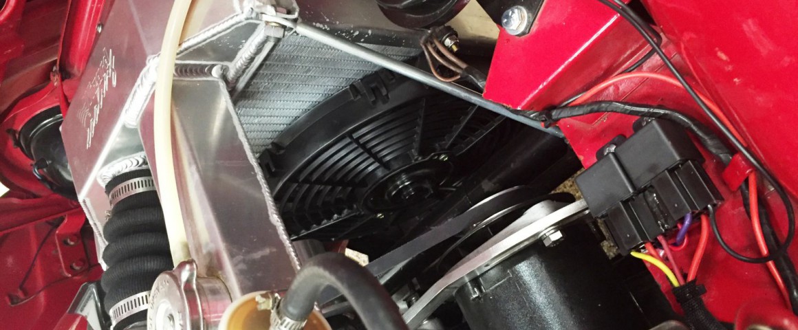
Zoomed out view with relays at the bottom and the electric fan on the radiator.

Zoomed in view of the two relays and connectors.

Original fuse block on the left with a second fuse block added for accessories. This is where I used a 20A fuse for the fan.

This shows the overdrive wiring coming from the gearbox (down) and to the overdrive switch (up). Notice that I replaced one of the single barrel connectors with a dual connector to easily allow me to tie in the yellow wire to the relay.

'Electric Fan Cycling Solution' have 6 comments
March 1, 2018 @ 6:28 am Matt
I like this idea but I would also include an auxiliary switch on or near the dash so the fan can be turned on if sitting in slow moving traffic with the engine running.
March 3, 2018 @ 2:09 pm Richard
I think the idea is that the fan comes on automatically when in first or second gear, but not when you are in third or fourth. Is that right Joel…? Then it would come on every time you were in first or second whether you needed it or not. Seems a bit easier to just add a thermal switch to me, but interesting option.
March 16, 2018 @ 12:40 pm Dale L. Olson
When I installed the fan on my 59 TR3A, I bought the adjustable temp bulb and switch. I mounted the sensor bulbit in the outlet air path of the radiator, with the adjustment under the dash. When the deal was done, I adjusted the switch to turn the fan on at around 190 degrees (Gauge indication). The power for the fan system was supplied by the ignition switch. This worked well for us, keeping the water temperature in the 190 to 200 degree range. If I were to do this again, I’d find an auxiliary water pump and set it so the pump and the fan running after the ignition was turned off until the water temperature reaches the fan shut off temperature.
June 26, 2018 @ 12:42 pm John Turney
My Austin Healey upper radiator hose is smooth and not the bellows style shown above. I cut a 1 1/2″ section out of the hose and installed an aluminum water temperature sensor adaptor with a temperature switch. Much easier.
November 30, 2018 @ 8:34 am steve
well i thought it was a great idea, nice to think up and design something yourself ,well done
August 21, 2019 @ 8:21 pm Steve
Back in the sixties I owned a ‘ 64 Spitfire. I removed the mechanical fan and fitted an electrical fan in front of the rad which switched on and off when required by a thermo. switch slipped into the header hose . Never had a cooling problem and gained a few horse power.