


Driving lights and fog lights came about as car owners navigated the twisting turning by-ways of misty England. Powerful lighting was necessary to illuminate the road ahead for potential hazards to be successfully identified and avoided. In addition, foggy and wet conditions caused by road spray obliterated the edges of poorly crowned roads. There is one more oft-omitted benefit to driving lights and fog lights, simply stated they are “racer cool”; installing these lights, however, on your favorite British sports car takes planning and preparation.

The fog lights are mounted and ready for power.
I remember the days when I rummaged about in my “box of wires” and grabbed any gauge wire of sufficient or insufficient length, splicing together a “rat’s nest” of wire connections and crimped ends to connect any number of desired accessories. After a few smoke-filled incidents I am much more careful.
My 1966 Volvo 122S may not be British, but it does use many components common to the cars of England. I picked up two vintage fog lights at a yard sale and these will be installed on my Volvo.
Let’s begin with your lights already mounted to the car, the wires dangling beneath or behind and waiting to receive power from Mr. Lucas. The first order of business is to determine the amperage of your driving/fog lights. My lamps are vintage and each unit reads 35 watts. The formula for amperage is watts divided by volts equals amps, or W/V=A. Since I will be wiring the lights to the relay with one lead, 70W/12V= 5.8A. I will be using 14-gauge wire, which handles up to 11.8A. Amps are a measure of current flow; volts are a measure of the force behind the flow of current. To protect my 14-gauge wiring I will be installing 10-amp inline fuses. The rule of thumb is this: the fuse ought to be rated near 80% of the amperage of the wire. This will ensure that you blow the fuse before you burn the wire. In my case, 80% of 11.8A is 9.44A so a 10-amp inline fuse is perfect.
I will need several colors of 14-gauge wire: black, green, white, and red. The reason is simple, the color identifies the purpose of each wire and if I ever have a problem I can track it down using my wiring diagram. Here is what I need to complete the job:
- Two 10-amp inline fuses (as above)
- Wire in the gauge and colors described
- Relay (with four male spade connectors on back)
- Switch (with three male spade connectors on back)
- Female spade connectors (crimp style)
- Eyelet connectors (crimp style)
- Butt connectors (crimp style)
- Electrical tape
- Lock ties (small black type)
- Crimping tool and cutter for wire
- Electric drill and a 7/64” drill bit
- Sheet metal screws (for connecting ground wires to body)

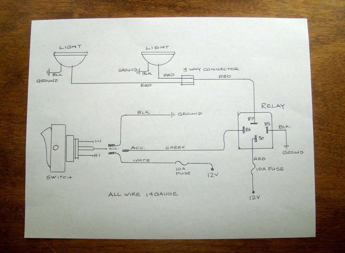
A tidy wiring diagram is a must.
Before cutting any wire, a good diagram is in order. Draw a diagram on plain white paper with wire gauge noted and colors identified. Each component must be labeled. This wiring diagram will stay with the car so make it neat and easily readable. Pictured is my wiring diagram for installing two fog lights with fuses, a switch, and a relay. If you need assistance drawing a diagram, refer to your car’s factory workshop manual (reprints are available from Moss). You’ll find examples of switches, lights, fuses—it’s helpful to understand and keep a universal language of the components in your drawings.
Relays are an important component in wiring fog or driving lights with a 30-60A draw. Basically, the relay protects the switch from getting hot and creating unwanted resistance. The low current through the switch triggers the relay to make a higher current connection to the heavy load of the fog lights. If you purchased your relay from a reputable source, it will have numbered terminals, which aid greatly in connecting everything correctly.

The relay location must be well protected.
The fog lights are positioned first, the switch second, and the relay last. Since the switch will be on the dash and the fog lights at the front of the car, the only location decision to be made concerns the relay. I want the relay in a protected place near the front of the car. It needs to be near a 12V power source. I have chosen a position on the inner fender arch away from heat, but protected from road spray.
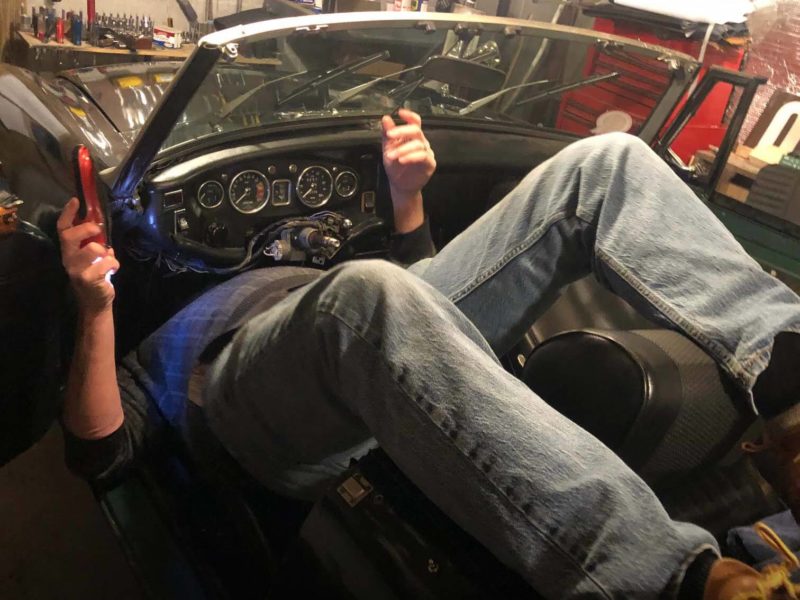
Use a test light to confirm your power sources for both the relay and the switch. I found a power source for my relay terminal number “30” on the low beam wire of the left headlight. I will splice into this wire so that my fog lights will work only when the low beams are on. I found a hot connection at the fuse block for the switch. Both of these 12V power lines need a 10-amp inline fuse.
Disconnect the battery!

A three way connection is made to the power source for both lights.
Now you are ready to run your wires according to the wiring diagram. Keep wires close to an existing wire loom and be careful of loops and sagging wires, which may snag on a moving component of the car. Do not add the crimped ends to any of the wires until all the wires are in place. Cut and leave about 6 inches of extra wire at every terminal point.
Start with the ground connections for each component. Locate a suitable body connection point and drill a 7/64-inch hole in the body. Crimp an “eyelet” connector on the ground wire and screw a sheet metal screw through the “eyelet” and into the body. This must be done for the switch, the relay and each of the fog-lights. The relay ground terminal is numbered “85”.
Drill the required hole in your dash for the switch; leave the switch free for the moment. I like to start wiring everything together at the switch and work my way toward the relay and the front of the car.
The switch has two remaining terminals. Connect a green wire from the “acc” terminal on the back of the switch to the number “86” terminal on the relay. The last terminal on the switch connects to the power source. This white wire will need a 10 amp inline fuse and is connected to the fuse block.
The relay is wired next. The power source for the relay is drawn from the low beam wire of the left headlight, as noted above. Splice a red wire from the headlight wire to the relay terminal “30.” This line needs a 10-amp inline fuse, so be sure and wire one in. The final terminal on the relay is numbered “87.” This terminal will carry power to the fog lights.
The fog lights each have two wires, one for ground and one for the 12V power. One of these wires from each fog light has already been connected to ground. A three-way connection must be made joining the second wire from each of the fog lights to the red wire going to the relay terminal “87.”
Finally, attach the switch to the dash and the relay to its location. A test is in order before you use the lock ties and button everything up.

Belighted Volvo!
Reconnect the battery
Turn on the ignition and hit your switch. Nothing should happen. Now, turn on your headlights to “low beam” and the fog lights will come on. Toggle the switch and see that the lights work properly. Use lock ties to secure all wires.
You are now ready to move about the country! Your lights will penetrate the fog and… they look “racer cool.”
By Ric Glomstad

'How To Wire Driving/Fog Lights' have 24 comments
August 9, 2012 @ 8:12 pm Ed Hargrove
Ric,
Compliments on a well-written and informative article, but I have to offer one criticism. Fog lights don’t penetrate fog. Fog is a problem for drivers because it reflects most of the light from standard low beam lamps, and much of that occurs because of the beam pattern, the way headlight lenses aim and disperse the light. Real fog lights, unlike the ones pictured in your article, mitigate the problem by using a very wide and uniform horizontal dispersion beam pattern with a sharp vertical cutoff that illuminates the road directly in front and the edges of the road, without a longer-range central blob of light like a headlight’s that would simply reflect off fog into your eyes. A fog light’s beam pattern does not help you see a long distance down the road. Nothing can do that in fog except maybe infrared or radar. For that reason, in heavy fog (meaning the kind where your low beams are not very helpful), to see an improvement you must turn off the headlights and turn on the fog lights. You won’t see very far, but you will see enough to proceed slowly and carefully. You don’t want to use both fog lights and low beams at the same time when there’s no heavy fog either, for 2 reasons: first, it’s annoying, verging on infuriating, to oncoming drivers when you shine 4 lights in their eyes instead of 2; second, it doesn’t do you any appreciable good, at most adding a little illumination to the road edges, which is useless at normal speed.
August 14, 2012 @ 2:36 am Han van Pelt
As Ed stated, fog lights are effective because it prevents stray light from being reflected back into the driver’s eyes. You must not use regular lights in combination with fog lights. While we won’t be driving our classics in snow storms, we will be driving our daily cars while the snow is falling. True fog lights, correctly used, are a fantastic asset during heavy snow falls.
September 13, 2012 @ 3:48 am Rusty Tools
Great write-up! Detailed and easy to follow, and a simple solution to a common question.
If I understand correctly, you have the power for the new lights tapped off the low-beam source, and the power for the relay coming from the fuse-block. Wouldn’t that load down the low-beam circuit even more? Would it be better to reverse them and have the new lights coming from the fuse-block and the switch wiring off the low-beam wire? Functionality remains the same.
Thanks
December 14, 2012 @ 2:30 am FinnishSmart
I agree – assuming the switch activates the connection between 30 and 87on the relay, I would have thought 30 on the relay should be connected to the fuse-block and the low current supply to the switch from the low-beam wire. Not that I’m an expert or anything but connecting the other way round as explained in the write-up would be basically the same as crimping both fog lights to one low-beam headlight which would result in blowing the headlight fuse(?).
September 21, 2012 @ 7:57 am Ron Dubiel
At the end of the article, you mentioned that foglights were “racer cool”. Many years ago, I was driving late at night on a rural country road in very thick fog. I had maybe 25-50 foot visibility. As I was coming around the mountain, all I saw was a single light. I jammed on my brakes just in time so I wouldn’t rearend the Volvo 1800. If he didn’t have a rear fog on the drivers side, the car would have been junk. If I put fog lights on my car, I’m saving one for the rear. Now that is “cool”.
February 26, 2013 @ 5:59 pm Ric Glomstad
I agree with the fog light/headlight comment from Ed. My goof! I wanted the driving lights connected with the low beams to be legal in Washington State…hence I tied the wiring as written. When all lights are “on” there would be an extra load on the low beam headlight switch as noted…it would be better all around to wire line “30” to a fuse block location and not to the low beam wiring. Thanks for the comments, guys. There are sharp folk out there! Now, I better rewire my system.
July 13, 2013 @ 12:30 pm Nicholas
A BIG THANK YOU !!!
Your article was the only one that i found on the web with clear and simple instructions
Cheers Nicholas
Sydney Australia
February 1, 2022 @ 8:17 pm Roy Malac
There is one fallacy in the write up. A 14 gauge wire can handle much more than the 11 amps stated in the article. Most houses use 14 gauge wiring in 15 amp circuits and sometimes in 20 amp circuits. But even in those cases the wire still is nor anywhere near its “burnout” current. The wire can carry a lot of amps and most wire ratings are based on limiting the temperature of the insulation surrounding the wire. The current carrying rating applied to wire gauges also is dependent on the ambient temperature. The higher the ambient, the less “permitted” current in order to limit the sustained temperature of the wire and its insulation. But even then, the wire still can carry much more current and even more if the duration is short. Current carrying capacity is dictated by the National Electrical code so as to limit how hot the wire and its insulation gets in a given ambient temperature for thermal safety reasons — not wanting to start fires. A fuse blows quickly. While 14 gauge wire is a god selection for several amps it is nowhere near its limit and the author’s selection of a 10 amp fuse to prevent burning the wire” is incorrect. He could use a higher rated fuse and still would not “burn” the wire — because the wire can carry a lot more than 11 Amos and the fuse will blow rapidly well before the wire “burns”.
February 6, 2014 @ 12:28 pm Robert
I’m attempting to learn how to wire some lights on my vehicle in the rear for backing up at night using a relay switch. This article was very helpful, as well as were the critical comments.
However, what struck me as the most awesome thing about this whole experience (and I believe I speak for many others who won’t take the time to comment) is the author’s humility. Faced with criticism (gentlemanly criticism, but criticism none-the-less), he remained humble and in the end learned something himself. That is what I would classify as “very cool”.
A toast to humility! May we all find the happiness that brings, and spreads…
(Proverbs 9:9) Instruct a wise man and he will be wiser still; teach a righteous man and he will add to his learning.
February 16, 2014 @ 2:16 pm Tom Pearson
I am a big believer in having a bright red rear foglight on my autos. Common in Europe as both factory equipment on some makes of cars and after market on others. Hella USA used to import a couple different rear fog lights and a really neat switch that could allow just the rear fog light to operate, allow just the front fog lights to operate and a combo of both. Alas, no longer availiable at least in the USA. I just installed a super bright red LED rear fog light that PIA has on my Subaru Outback. Wired to work separately or with front factory fogs. The PIA unit is somewhat expensive but far less than having some idiot smack you in the rear in foggy weather because he was driving too fast for conditons.
May 7, 2014 @ 5:39 am Alex
Nice write up!
I am wiring a pair of hella driving lights on my 68 122s, and I can’t figure out where on the fuse box I should be going with the wiring. Do I have to cut in to the wires at the head lamps to make the driving lights work?
Thanks
April 16, 2015 @ 5:02 pm Sonia
Hello,
I want to wire (5) LED spot lights to one switch, each light has puts out 35 watts and my jeep puts out 12.25 volts.
Can I do this using one switch?
How many fuses do I need and what size?
Can all 5 use the same relay?
Do u have a diagram for this application?
What size Guage do I need?
Can I connect all 5 red wires together then run one single red wire to the engine compartment? (Same for the black wires?)
May 14, 2015 @ 10:41 pm alfi
Do you need to earth the switch because it has a light to indicate it is on? If not then why?
May 15, 2015 @ 4:10 am nikasj
The switch should be grounded.
March 11, 2016 @ 7:15 am Jcoleman
HI, instead of a 3 prong switch can i use 4 prong switch for spot lights
if so can you tell me what prongs i use for the wires
April 1, 2016 @ 10:16 pm Richard Maitia
My hat is off to the author very nice accepting constructive criticism and learning like the rest of us. Also thanks to the person correcting or adding additional information, many would have gone and said nothing. A nice plus for those that do not know.
May 3, 2021 @ 6:06 pm Keith Havard
Amen
July 22, 2016 @ 7:45 am Cesar Solorio
Great post man! Helped me a lot since I’m going to be installing fog lights in my car this weekend! Thank you!
September 27, 2016 @ 10:51 am 2
I am writing to ask a follow-up question about the gauge of wire for my Austin Healey Sprite MkI lighting. I know that 16 gauge is too large because that is used for several non-lighting circuits in my Sprite. Can you tell me the specification for MkI Sprite lighting? It is probably 14 gauge or 12 gauge. (I have an original BMC Workshop Manual, but it doesn’t mention wire gauges.)
Thanks for your article and work for sports car owners.
Sid Nau
Kansas City, Missouri
January 12, 2019 @ 3:36 am Jack Hemming
Having recently purchased from Moss a relay kit single GAC4027 to wire spot lights on my MGA with positive earth.
Should I change the relay connection of 85 and 86. Also is a 2 connection switch OK ?
April 22, 2019 @ 12:21 pm Dwight Magee
Hi, I purchased a Moss relay kit for my headlights and it works great. I recently purchased two driving lights
Can I join these driving lights into the high beam relay so they operate off the high beam switch along with the high beams?
December 28, 2019 @ 5:57 am DingusDan!!
I just want to know how to take a set of LED fog lights. Inteded for a vehicle and instead wire them to a normal household plug in and make them work?
August 30, 2020 @ 7:15 am Larry Vern
Thank you for the info. Explained very well.
My 350 ML Benz has factory fog lights and I often drive at night with both headlights and fog lights even without fog as the fog lights help reveal the infamous Jersey pot holes. And I agree also looks cool.
February 1, 2022 @ 8:27 pm Roy Malac
The wire gauge selection should be based on limiting the voltage drop between battery and the load (lights). Smaller gauge wire has more voltage drop and more resistance. The length of wire also adds drop and resistance. You can find recommended “max” length and wire gauge size voltage drop and resistance tables on the internet. The table recommendations use very conservative limits on heating of the wire and its insulation and minimize voltage drop.