


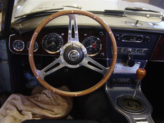
I spent a couple of hours today installing a Moto-Lita steering wheel on an Austin-Healey 3000 BJ8. This car was equipped with the original adjustable wheel, which was optional on some models. It is nearly the same as what came on many Triumph TR3s.
In some ways it is easier to install the new wheel on a car with the adjustable steering wheel than on the seemingly simpler non-adjustable model. The adjustable version has a collar than can be loosened allowing the already too close wheel to be brought even nearer to the driver. This can be advantageous if the driver has large thighs…don’t worry ladies, this includes just about everyone except Twiggy.
The old wheel and hub must be removed before the new wheel and hub, or “boss” as Moto-lita likes to call it, can be installed. Well, duh! The “trafficator” or control head is reused, making the new wheel look like a factory option. The instructions that come with the hub are completely useless, and refer to some vehicle that probably does not exist, even though the hub is specially designed for the A-H 3000…typical British humor.
 There are a couple of ways to get the control head out of the car, so as to remove the old wheel and hub. The most obvious way is to disconnect the wiring at the steering box and pull the control head out with about five feet of harness. The trouble with that is the bullet connectors at the end of the harness will not fit through the tube that runs through the steering column. Some of them will have to be cut off in order to remove the control head and harness. Then try and fish the bastard back through…hah!
 My favorite approach to this problem is to disconnect the wires at the control head, leaving the harness in place. This makes some sense, since the control head probably needs servicing, anyway. Note that this takes calm nerves and a steady hand…about three beers will do it. Before getting started, be sure that you have determined the “straight ahead” position of the old wheel. If your wheel is not straight, this is a good time to correct its position. Also, check to see if your horns and directional signals work, including the self canceling feature. This is an opportune time to fix any problems with these features. Here we go!
 Disconnect the battery. With the wheel adjusted as far away from the driver as possible, back off the three tiny grub screws around the “big” edge of the old hub. This will release the control head, allowing you to pull it several inches towards you. The control head is attached to a two-part metal disk with a short tube coming out of it. This whole assembly moves back and forth when the wheel is adjusted, with the short tube fitting in a notch in a smaller tube that runs the length of the steering column. This is what holds the control head in position, keeping it from spinning when the wheel is turned. The part of the disk that rotates is locked to the hub by the grub screws and has a finger to operate the canceling mechanism.
 Take a few minutes to familiarize yourself with the control head before proceeding. It is a lot simpler than the description! There are three little countersunk flat head screws that hold the Bakelite switch to the metal part. There are also three holes in the rotating disk that will allow access to these screws. If you look closely, there is a plate that hides the screws with a tab to keep it from turning. Pretty devious, huh? Lift the tab and spin the plate to gain access to the screws. With all the holes lined up, use a very small and short screwdriver to remove the screws. Don’t lose them!
 With the two components separated, you can see the four little wires that are attached to the switch with tiny nuts. Carefully pry the horn push trim ring out of the face of the control head. Put the trim ring, button, and spring in a safe place…note that the button and ring are keyed, and will only go in one way. There are two brass screws that hold the horn contacts in place. On the backside you will see that one of these goes with the nut holding the brown horn wire, which you can now remove. Put the nut back on the screw for safe keeping, and to hold things together. The other three wires are for the turn signals. Note the location of each wire and be sure that you can identify each one for reassembly. You must have the turn signal lever positioned over the nut that you are removing when you remove the wire, or the screw will fall into the mechanism. Put the nuts back on the screws before moving on to the next wire.
 Cutting those damn bullets off is starting to sound mighty good. Never mind, the hard part is pretty much over. Straighten the four wires out and gently pull the short tube away. Leave the control head parts to soak in paint thinner while you do the rest of the job. If your turn signals have not been canceling, a brave (foolish?) person can completely disassemble the mechanism and probably fix the problem…often an accumulation of dirt.
Slide the old hub towards you until it hits the cir-clip at the end of the column. Use a pick to coax the clip out of its groove while pulling the hub towards you. Congratulation, you are half done!
 Now is as good a time as any to attach the Moto-lita wheel to the new hub. Sandwich the wheel between the trim ring and the hub with the umpteen screws, nuts and washers provided. Note that the top of the hub is marked, and that the wheel can be positioned with spokes oriented according to the owner’s lack of taste. Place the assembled hub on the column after applying a little anti-seize compound. Play with the adjustment until you are comfortable with the driving position. If you like it closer to you, put the chrome trim spring and end cap back on the column before final mounting of the wheel…this will cover the exposed splines. At this point, it might be wise to take a spin around the block to check the straight ahead thing.
Dry off the now squeaky clean control head parts and oil lightly. Reassemble in the exact reverse order. Note that the little tab on the wire ends fit in little hole next to the screw. And don’t forget to keep the lever over the screws while the nut is off! Check that the horn and blinkers work after the wires are reconnected (you will have to temporarily ground the brass ring on the back of the switch). Reconnect the battery and try again.
Line the canceling finger up with the bottom of the assembly, before pushing the control head into the hub and locking in place with the grub screws. You may have to pull the hub slightly towards you to get the head to go fully home. Tighten the Allen-head screws to lock the hub, sell your old wheel on Ebay for big bucks, and enjoy!
By Mike McPhail
Gulf Coast Austin-Healey Club
Hill Country Triumph Club


'Pint Size Project — Replacing the Steering Wheel' have 4 comments
November 1, 2017 @ 1:32 am GUY EDELSBURG
HI
I HAVE 1977 RUBBER BUMPER MGB
WHAT IS THE SIZE OF THE STEERING WHELL NUT? I HAVE TO REMOVE IT AND I HAVE THE MOSS PULLER
April 17, 2018 @ 10:02 am Pat Spencer
I have a ’78 and have tried everything (Blaster, WD-40; Kroil; tapping the steering column while pulling; staring at it until I was cross-eyed; and the special tool designed to do this job on 77-80 MGB). The steering wheel has not budged. It has become a test of will and so far the car is winning. I used a 26mm socket on the restraining nut.
December 16, 2017 @ 7:22 am John Wynd
Nice article on a subject that is so poorly covered elsewhere. It would be nice if the article was rewritten without all of the cutesy comments for someone who simply wants to remove, repair, and replace a balky control head. Step 1, step 2 ……….. And so on .
December 19, 2017 @ 3:03 pm stuursmad
Some of us like banter within our tech articles. It reminds us that these are real people investing time and having fun while helping others.