


Cleaning, Prep, Machining and Assembly
WHAT YOU CAN CLEAN YOURSELF
The rule with engine building is clean, clean, and then clean some more. Items that don’t move, like valve covers, front and rear engine plates, lifter covers, timing covers, distributor bases, etc., you can clean yourself. First, scrape off old gaskets as much as you can, then move on to degreasing. A parts washer makes this job a lot easier, but if you don’t have one you can make a temporary parts washer out a 5-gallon bucket and waterbased degreasers. Use rubber gloves, even water-based chemicals can be harsh on skin. There is no need to hurry; time is your friend when degreasing. Sometimes old paint will strip off if soaked long enough.

I like to get parts down to bare metal, because painting over old paint is a mixed bag of nuts. You can get a reaction between different paints causing wrinkling. A bead blast cabinet is ideal for this job; however a wire brush on a drill, or bench grinder with a wire brush will get the job done.
Wear eye protection.
Larger and the vital internal parts should be cleaned by professionals in an industrial parts washer.
WHAT A MACHINE SHOP SHOULD DO
A trip to the machine shop requires a plan. As much as I would like to say you can leave it all in their hands, you can’t. You have to have a good idea of your expectations and an understanding of the steps required to get what you want. Don’t let any steps get overlooked.
Engine Block
Check the straightness of the top of the block’s deck where the cylinder head attaches. If the surface isn’t flat, have the deck resurfaced. It’s okay if areas around the water jacket do not completely clean up. Surfacing them smooth will result in more material being removed than needed.
A word of caution about decking the block too much: Some engines, such as the Spitfire and Midget 1500 and the later TR6, have necessary recesses around the cylinder bores. Remove no more than .010″ so that the head gasket will seal properly.

Piston-to-cylinder wall clearance must be checked. If the gap is too big, have the cylinders bored and new oversize pistons fitted. Discuss with the machine shop the piston size. They will measure the new pistons to bore the cylinder. After boring, your block will be honed to get the proper finish on the cylinder wall. Finally the machinist will use a special tool to chamfer (angle) the tops of the bores. This is done to prevent a piston ring from getting caught and breaking during installation.
Line boring is not needed in most street engine rebuilds. Line boring insures that all crank journals are in perfect alignment and properly sized.
Many British engines have cam bearings in the block. Replace them. A new set isn’t expensive. I prefer the fullcircle cam bearings and not the split type, and the machine shop has the special tools and knowledge to do it right. Bring in the camshaft you are using to insure it fits with the new cam bearings. Sometimes honing is necessary to get the proper fit.
 Crankshaft
The car service shop should magnaflux your crankshaft to rule out any cracks. Magnafluxing typically involves applying a fluid, or powder to the crankshaft, then viewing it under a black light. The magnaflux chemicals help the machinist detect cracks. It takes a trained eye to do this procedure.
The crankshaft needs to be measured for wear and sizing. If your crankshaft is out of spec and has to be reground, there are several under-sizes of crankshaft bearings available.
Crankshaft grinding is a very skilled part of the machine shop phase. You will want to ask around for the shop that has the best reputation for crankshaft work. I tell my customers to go where the racers go. It is extremely important that the filet radius (the edges of the journal where it joins back into the crankshaft body) is restored when the crank is reground. This is where most cracks occur, so the proper filet radius is important for the overall strength of the crankshaft.
 Connecting Rods
The big end of the connecting rods that clamp around the crankshaft need to be checked for sizing. Some connecting rods have floating piston pins, the bushings will need to be checked for play and wear as well. As a rule of thumb, it’s best to replace the rod bolts. Your connecting rod will almost always warrant big end resizing, and considered a must if you replace the connecting rod bolts. You may also have to replace your connecting rod small end bushings as well on a floating rod type.
Some connecting rods will be a press fit type, and not need servicing other than pressing the old piston off and the new pistons on. If your engine has press fit piston pins, like MG 1275, or the later MGBs, this is not something you can do yourself; it requires special tools. Pushing out the old pins is normally done by cold pressing. Installing new piston pins and pistons require a rod heater, where the rod is heated to about 1200 degrees and then the piston and pin is installed on that rod quickly before it cools. Without question this is a job for a professional.
Flywheel
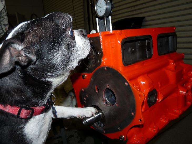
If you can catch a fingernail on the surface of the flywheel where the clutch disc rides, you will need to resurface your flywheel. Inspect your starter ring gear. If it is worn, have it replaced as well. Your machine shop can easily do this for you.


 Cylinder Head
For most, dropping off the cylinder head complete to a machine shop is the best idea. They can handle the disassembly, cleaning, checking for cracks, machining and assembly for you.
Most cylinder head parts are inexpensive. I recommend replacing valves and valve springs. I don’t like refacing valves. If the margin (the vertical part of the valve just below the seat sealing area) is ground away during refacing it could leave a sharp edge that can lead to a burnt exhaust valve later on. Inspect your valve guides next. The OEM guides are cast iron. Manganese bronze guides are also available and I almost always use them because they are very long wearing. Manganese bronze guides expand with heat at a different rate than your cylinder head and require more clearance than cast iron guides. I use .003” clearance on my manganese bronze guides. This may seem like a lot of clearance to your machinist who is not used to working with our engines. But improper clearance can result in a seized exhaust valve.
Hardened exhaust seat inserts are a must for the hotter burning unleaded fuels used today. Regrinding the original cast iron exhaust seat is a short term answer, as valve seal will be lost in a short period of time. Intake valves don’t require hardened seats since they are not subjected to intense heat. The only reason you would install valve seats on the intake side is if a cylinder head has had many valve jobs in its life. The intake will have receded. A better solution is to use this as an excuse to use larger intake valves and enjoy improved performance.
Cutting the valve seats: The most common is a three angle seat for better performance and sealing. Most machine shops have a special tool that can cut all three angles at the same time.
The shop will most likely resurface the cylinder head to insure flatness, and provide for a good sealing surface for the head gasket. I highly recommend Moss’ uprated valve seals.
At this point the machine shop is ready to assemble the cylinder head. They will weigh the valve springs and use shims as needed to insure the correct valve spring height and seated pressure of the valves and springs.
Rocker Assembly
It’s a good idea to replace the rocker shaft. Inspect the rocker arm bushings and replace if needed. Check the wiper section of the rocker arm where it makes contact with the valve stem. If you find excessive wear your machine shop can reface them. New rocker arms are not expensive and in many cases less than the cost of having your originals rebushed and refaced.
Other Areas of your Engine
If your engine has a harmonic balancer, it will have a rubber insulator between the inner and outer rings. The rubber insulator can crack and wear out over time. A balancer can be rebuilt or you can purchase a new one and in some cases a high performance harmonic balancer is available. I use a Moss high performance Pro Sport model on my MGB racecar and can attest to its high quality.
Oil pump – whether you replace with new or reuse your current oil pump you will need to disassemble it and check the clearances. Your manual will tell you the clearance specs, and you need to use an assembly lube on all moving parts inside the oil pump. Never assume a new oil pump should not be taken apart and checked.
Clearances and thoughts
Just because your cylinder bores or crankshaft journals “look” good, never assume they don’t have any wear or issues. Have them measured by your machinist.
If your crankshaft is being reground and your connecting rods resized, this is time to use the size spec range to get the proper rod bearing clearance. For most of our engines .0015″-.002″ is ideal for rod and main bearing clearances. It’s important that this be accounted for because too much clearance would cause a loss of oil pressure and too little clearance could cause damage to the bearings and crankshaft.
“Blueprinted” engines are achieved when a builder dictates these sizes to get the exact clearance they need. Proper clearance is required in many areas of your engine—piston to cylinder wall, crankshaft end float, camshaft end float, connecting rod side clearance, and then also things like spring valve lash. Blueprint clearance is mostly done by more advanced engine builders, but your machinist can measure and machine everything to spec.
NEW PARTS
The following is a list of new parts I typically include in an engine rebuild.
Bottom end
• Piston set – these will come with rings and pins supplied.
• Crankshaft bearings – for the connecting rods and main bearings. I prefer tri-metal bearings; they are what the factory originally supplied for many cars. Thrust bearing in the proper size.
• Crankshaft – replace your pilot bushing. On some crankshafts the area where the seals ride can wear over time and new seals alone may not insure you won’t have leak. A Speedi-Sleeve can be used to renew the surface.
• Cam bearings – I prefer the full circle type
• Rod bolts – I recommend replacement.
• Camshaft – if needed/desired. This is a good time to consider a performance cam.
• Lifters (tappets) – are always replaced with a new camshaft. If you are reusing your existing camshaft your lifters can be reused if they are in good condition. Remember they have to go in the exact spot they came out of it. You can use new lifters with a used cam but never used lifters with a new cam.
Cylinder head
• Intake valves – Consider oversize for better flow
• Exhaust valves
• Valve guides
• Valve seals
• Valve springs
Rocker arms assembly
• Rocker shaft
• Rocker arm bushings, if needed
Gaskets and the final touches
• Engine gasket sets – I prefer Payen brand gasket sets when I can get them.
• Timing assembly – always replace the chain, timing gear and timing chain tensioner. If you have a single row chain I suggest you upgrade to a double row chain if available.
• Seals – should come in your gasket set but double check.
• Oil pump
• Oil pressure regulator parts – They are inexpensive, so replace them.
• Water pump
• Clutch kit
ASSEMBLY
Keep your manual close at hand for the assembly stage. It will be your main point of reference. I hope this far into the game you already have a good manual. I won’t cover every little detail that a manual will tell you about engine assembly. Instead, I’ll tell you about steps the manual may not cover, and about the engine assembly sequence that can be helpful to you.
All engine parts are cleaned, prepped and machined or new. And, once you have the engine block on the engine stand, you’re ready to dive in.
 Test fitting the crankshaft and bearings
Install the main bearings in the block with just a thin coat of non-synthetic 30WT motor oil, then install the crankshaft and coat the exposed journal with oil. Third, install the main bearings in the main caps—but don’t install the caps yet. You need to plastigauge the bearing clearances. From your local part store you will need to purchase the green plastigauge with a measurement range for .001″-.003″. Cut a small piece of plastigauge and place on the #1 journal. Coat with oil, install and torque the #1 main cap to manual specs.
Carefully remove the main cap and use the graph on the paper slip the plastigauge comes with to determine the clearance. .0015″ to .002″ is acceptable. Do this one main cap at time working from front to back being careful to not rotate the crankshaft. Now that you have acceptable readings on the main journal make sure you clean the plastigauge off each crankshaft journal and bearing shell. Remove the crankshaft.

 Install the crankshaft and bearing
Purchase a good quality assembly lube. Lube should be used any place one part makes contact with another that could cause friction—the exception being the piston and cylinder walls. We will cover that later.
Install and torque the main caps one at time. I like to start with the center cap. Once you torque it to spec turn the crankshaft by hand, you should feel a nice fluid motion without any binding. Make sure you use assembly lube on every main cap and your thrust washers as well. Once the crankshaft is installed, be sure to check your crankshaft end float as I first discussed in the disassembly article, and make sure it is in spec per the manual.

 Install the piston and connecting rods
You will need a piston ring compressor. Apply 30W motor oil to the cylinder walls and the piston skirts. Use the ring compressor around the piston at the point where the rings are located on the piston to compress the ring as it would be when in the cylinder. I start with the #1 piston. Make sure your crankshaft is at BDC (bottom dead center) meaning the crankshaft journal is closest to bottom of the engine. Take the connecting rod, with the cap removed, and the rod bearings installed and insert the connecting rod in the bore. Make sure the piston is marked “front” and that you are installing it in the proper direction.
Once the piston gets to the point where the ring compressor is resting on the deck of the block use a dead blow hammer to tamp the top edges of the ring compressor to square it against the bore. Use a wooden, or plastic hammer handle, to tap the top of the piston down into the bore. Make sure you keep the ring compressor firmly against the block deck. The piston should now slip into the bore. If you feel any resistance, make sure the ring compressor is tamped square against the block deck, and if you still feel resistance, you may want to look in the bottom of the block and make sure your connecting rod is not interfering with the crankshaft.
Once all of the pistons are in you can rotate the engine to the access the bottom side. Follow the same process with the rod bearings as we did with the crankshaft and plastigauge each journal one at a time. Once you have finished the plastigauge procedure, and cleaned it all up, make sure to use assembly lube on your rod bearings and install your rod caps. Lube the rod bolt threads with motor oil or fastener assembly lube, like the one ARP makes, and torque your rod bolts to manual spec.
Handy Tip: Use a Sharpie to put markings on parts you have already torqued or checked clearance to know where you are in the process.
 Install the camshaft, front engine plate and cam thrust plate
Cover the camshaft journals, lobes and gears liberally with assembly lube. Be extra careful installing the camshaft into the block—especially with a block that has cam bearing as most nicks and scratches happen during installation.
Install the cam thrust plate, timing gears, chain and tensioner (if applicable) following the workshop manual guidelines. Line up the dots on the two timing gears when installing the chain.
If you are using a performance camshaft you may have to advance the cam timing per the cam manufacturer’s instructions. Altering the factory cam timing can be done in one of two ways—either by using offset camshaft keys or with an adjustable camshaft gear. Most cam lifters can be installed after the cam, but on the MG and Austin Healey A-Series engine, the lifters have to be installed before the cam is installed. Pay close attention to your workshop manual for tips like this. They could save you a big hassle later.


 Degreeing a camshaft
It’s really more simple than people make it out to be. You need the following to do the job:
• Degree wheel
• Pointer – this can be as simple as a piece of wire bolted to the front side of the block. It should come around the outer edge of your degree wheel, preferably on the top side.
• Dial indicator on a magnetic base
With the degree wheel and pointer installed, put the magnetic base on the top of the engine block surface or deck. Position it toward #1 piston and then bring the piston toward the top of the block. What you are looking for is the point the dial indictor needle quits moving as the piston comes to the top of the block. Now that you have found TDC, move the dial indictor’s outside bezel to reflect zero at the needle point. Now loosen the crank nut and rotate the degree wheel to reflect TDC on it. Double and triple check this to make sure you are at TDC. This is very important, because if you are not on TDC, all your readings will be wrong.
Install a lubed lifter on #1 cylinder intake and then install a push rod into #1 intake lifter. Set your dial indicator on the top side of that push rod. The goal is to find maximum camshaft lift on the indicator. Rotate the engine by hand; I like to do this from the rear of the engine as to not disturb the degree wheel’s setting. Move the crankshaft the normal operating rotation (clockwise when facing the front of the engine) until you see the needle reach maximum camshaft lift. Zero out the indicator and double check to make sure you are correct. The goal is to spin the engine in the normal rotation to maximum cam lift (now zero on the dial indicator) and stop at same given point before and after max lift has been achieved. This number could vary, as long as it is the same exact point before, and after maximum lift. I use .005″ before and after maximum camshaft lift. Make sure each time you do this you rotate the engine counter-clockwise approximately .100″ and then start back in the normal rotation of the engine—this will make sure there is no timing chain slack that could skew your readings.
Now stop at .005” before the indicator reaches zero, or maximum lift, record your readings at the degree wheel. Move to zero and then around and stop at .005” past zero. Record your reading. Add those two numbers together and divide by two—that is your cam timing.
Chances are your cam timing is probably not where it needs to be. But now you will know what degree of offset key to order. If you are using an adjustable cam gear then you can do all of this without removing the timing gears again unlike a offset key which can have +/- 1-2 degree tolerance range. Adjustable cam gears will have about 20 degrees of variable adjustment to work with assuring you can get the cam timing exactly where you need. An adjustable cam gear is really worth it if your budget allows.
Handy Tip: If using an adjustable cam gear, torque the cam retaining nut to manual specs before making your adjustments. The bolts holding the adjustment on the cam gear are small (¼”-28), and if you torqued your cam retaining nut later, which has a much higher torque spec, you could overpower the smaller bolts and change your cam timing.
 Check your camshaft end float
You will do this similarly to your crankshaft end float. Set up the magnetic base and dial indicator on the front side of the cam, or cam gear, and moving the camshaft front to rear reading the movement on the indicator. Refer to your workshop manual for the proper spec but it will likely be .002″-.005″. If the gap is too big you are going to have to shim the camshaft or remove material from the back side of the cam gear.
Oil Pump and Exterior Assembly
Install the oil pump, remember it is important to disassemble the oil pump, clean the inside whether new or used, lube them, and check the clearances on them per the manual specs. Make sure to lube all points of contact.
Install all bolts on the exterior of the block, for example, threaded plugs, oil pressure regulator, distributor drive and base, water pump, timing cover, crank pulley, motor mount brackets and seals (always put grease on seal lips to avoid damage during installation). Install the oil pan and gasket.
Install lifters, pushrods and cylinder head
For engines with a lifter cover or external lifter access, install the lifters—if not already pre-assembled. Next, install the cylinder head. Make sure all stud and bolt threads are oiled. It is a normal practice to oil the threads on all engine high torque bolts to help reach true torque. Once the studs are installed (if applicable) then install the head gasket. Follow the advice of the head gasket manufacturer in regards to coating. For example, most modern black composite material head gaskets require no coating or sealer. If you are using a copper gasket then use a copper gasket spray coating. Install the cylinder head and rocker arm assembly. Rotate the engine by hand at the front crank bolt and adjust all your valves to the recommended lash for the camshaft you are using. If using a performance aftermarket cam, it may be different than what is listed in the manual.
THE FINAL LAP
• Install the valve cover.
• Mount the rear engine plate, flywheel and clutch.
• Install your newly rebuilt engine in your car.
Initial start up
Fill the engine with all fluids.
Be sure to use engine oil with 1200 ppm of ZDDP to insure long engine life.
Check for oil pressure before cranking. Remove the spark plugs and turn the engine over until you see oil pressure at the gauge. This may take several minutes. Take your time and give your starter a break if it takes a while. Never, ever fire up an engine without confirming you have oil pressure.
Once you have confirmed oil pressure you are ready to fire the engine for the first time. Have your timing light ready to set the timing. Once the engine starts you want to set the idle at approx. 2,000 rpm. Let the engine run 20 minutes at 2,000 rpm to break in your cam and lifters.
During break-in, check for leaks. After your 20-minute break-in, do your final tuning. If all checks out take the car for a short drive (don’t stray far from home, just in case) varying the rpm from 2,000 to 4,000. Make sure the engine does not overheat. After a few heat cycles, you will need to retorque the cylinder head and re-adjust the valve lash.
About the Author: As an engine tuner and builder for more than 30 years, Hap Waldrop is the go-to guy on British car forums. His advice on road cars and racers is often the last word. Hap owns and operates Acme Speed Shop out of Greenville, SC, where his specialty is rebuilding MG engines ranging from stock to full out race prepared. To read Hap’s previous article on engine disassembly and inspection, visit www.mossmotoring.com/disassembling-british-engine


'Restoring a Classic British Engine' have 5 comments
October 16, 2013 @ 2:20 pm Scott Sewell
This is really useful and clearly written. Thank you very much!
July 19, 2014 @ 4:35 am Ray Ciccarelli
Hello
Good information. This information does not touch on replacing the Piston sleeves(Liners) and the figure 8 gaskets. Which is a big part of a rebuild,
and you mention getting new sleeves and piston sets.
Ray
July 19, 2015 @ 6:14 am Hap Waldrop
Ray, that is a good point, the wet sleeve motors like the Triumph TR3/$ engines are not a engine I work with. Maybe Moss Motoring can find a engine builder that specializes in these engines to do article on them, I know I would read it with great interest.
August 25, 2016 @ 9:30 am Planning for Rebuilding the Engine on the Spitfire | Triumph Spitfire Mk3 Restoration Project: Bruce's Triumph Therapy
[…] http://mossmotorsltd.wpengine.com/restoring-british-engine/ […]
January 13, 2018 @ 5:01 pm Pat Garity
Hap, Great article but I must disagree with method for finding TDC. I used to do it your way but a lecture by Dimitri Elgin pointed out that using a dial indicator can lead to errors. We know as the piston idles around TDC the cranks motion doesn’t produce much stroke so the positive stop method is more accurate and easy too. A piece of angle iron drilled and tapped with a small bolt installed across the bore is easy to make. Then rotate the crank til it stops, note the reading on your wheel then rotate it backwards. When you achieve the same degrees BTDC and ATDC your wheel will show TRUE TDC. Do both methods and you will see the dial indicator method can lead you astray by a couple degrees.