


A word of caution: working on automobiles is potentially dangerous, as is swimming in the ocean, snow skiing, and grilling hamburgers. The following procedure requires experience and commonsense. A post-graduate degree wouldn’t hurt either. ~Ed
Repair of a Mechanical Temperature Gauge
By John Neumeier
In 1984 I arrived in San Diego with a duffel bag and a few boxes, ready to study Physics at UCSD. While searching for a reasonably-priced car, I ran across a Thrifty Nickel ad for a 1967 MGB. When I spoke to the owner, he interviewed me in order to determine my knowledge about MGBs and cars in general. After passing his “test,” he “invited” me to inspect the car. The rear bumper and trunk lid were damaged in a minor accident, it had a few mechanical issues, and there was no top. The missing top was no problem in San Diego. He filled me in on the repairs he’d done through the years, and we agreed on a price of $500. For another $500, an auto body repair shop did the body work, painted the entire car in its original primrose yellow, and made a new tonneau cover. For a modest investment, I had the perfect car for my next five years. A few months before leaving the area, I purchased a Bentley shop manual from a woman at the flea market. It was a spare, to augment my Haynes manual. In 1996, I opened it for the first time, finding some notes inside, including the serial number of an MGB, which matched that of my car. I had purchased the repair manual from the previous owner’s spouse!
For 24 years the car was stored with friends, or in my own garage. I drove it occasionally while living in Los Alamos, Boca Raton, and Bozeman, Montana, where I now live. In 2014 I acquired a used overdrive transmission on a trip to the east coast, and the following summer I removed and rebuilt the motor. Naturally this project grew in scope, as such things do. One of the items needing repair was the temperature gauge. Once I learned how it worked, the repair seemed like a challenge for someone interested in physics, thermodynamics, and the general subject of “how things work.”
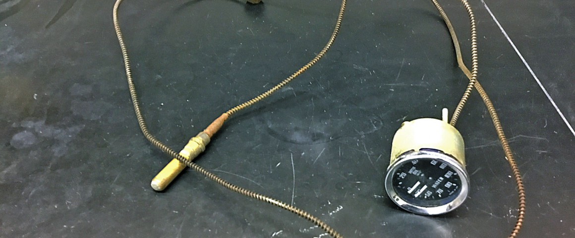
Modern automobiles utilize a sensor containing an electrical resistor that is placed in contact with the coolant in the engine block along with a dashboard gauge. American vehicles built prior to the mid 1950’s, and many older English vehicles built prior to the mid 1970’s, used a different method of measuring engine temperature. It is a closed system consisting of reservoir, capillary, and a Bourdon tube encased in the dashboard gauge housing. This closed system contains a small amount of a diethyl ether. Diethyl ether has the chemical formula (C2H5)2O and a boiling point of about 93˚ F (34˚ C) at standard atmospheric pressure. In the operating temperature range of an engine, the diethyl ether coexists in two phases—vapor and liquid. As the temperature increases, more liquid transforms into vapor, and the pressure in the closed volume containing it increases. The relationship between temperature and pressure in a constant volume containing diethyl ether is shown on the following page. The Bourdon tube is a flattened thin-walled tube formed into an arch. It is closed on one end, with the other end connected to the capillary. When the pressure increases, the closed end of the Bourdon tube moves in an arc, which causes the temperature needle of the gauge to deflect. It is calibrated to indicate the engine’s temperature. The unique pressure/temperature relationship of diethyl ether is essential for the proper function of the temperature gauge. As an interesting side note, the Bourdon tube measuring oil pressure in the dual gauge is identical to the Bourdon tube used for measuring temperature.

Disassembly
The Bourdon tube is inside of the gauge housing mounted in the dash. Ideally, the gauge housing need not be disassembled (see the section on Testing the Gauge and Calibration). Soft soldered to it is the capillary and the capillary’s other end is soft soldered to the reservoir. The capillary is made of copper-nickel alloy. It has an outside diameter of about 1/16″ and an inside diameter of about 0.015″. Filling the capillary and reservoir requires it to be removed from the gauge, which can be done with a hand-held solder iron (see Figure 1). A flame should not be used, since diethyl ether is extremely flammable. The gauge itself will become hot, holding with a leather glove or a vise is necessary. Once unsoldered, old solder should be cleaned from the capillary’s end by heating, and use of a wire brush. Clean the excess solder from the gauge with a solder pump. Or you can use the physics principle of inertia—heating the solder to the melting point, and shaking it out. Use a 1/16″ drill bit held between your fingers to open the hole at the gauge to allow the capillary to easily be inserted. About 0.15″ from the point where the capillary is inserted, there is a tiny hole that is perpendicular to the capillary. This hole should be cleaned of solder using a small drill or other means. It is a viewing hole, that will be used later to tell whether you have sufficient solder to properly seal the capillary in the gauge.

Searching for Leaks and Inspecting the Capillary
Make sure that the capillary is not obstructed. I used 0.012″ piano wire to probe the entire length of the capillary. Remove any sharp bends prior to feeding the piano wire through. Air from a compressor can be applied with adaptor hoses while submerging the capillary and reservoir in water to check for leaks. The reservoir has a soft-solder seal at the far end with a brass plug. This may be how the gauge was filled at the factory. The plug, or the solder joint near the middle of the reservoir, could be sources for leaks. If the plug is drilled out for repair, a small brass screw can be soldered in place to reseal the end.
Filling the Reservoir
Diethyl ether is a controlled substance, but small quantities can be purchased on eBay. There are also YouTube videos illustrating how to distill it from aerosol starting fluid. There are many liquids containing the name ether, diethyl ether, (C2H5)2O, must be used. It has the appropriate pressure/temperature relationship for which the Bourdon tube is constructed. Having a least six milliliters on hand will be good, but twice as much would be better, just in case. Work in a very well-ventilated area, in the presence of no flames or sparks. Fill a bucket that is deep enough to fully immerse the reservoir with water and ice. Have a means of securely holding the capillary and syringe for the remainder of this process, perhaps by mounting them on a wooden board with a few screws and some mechanic’s wire. The gauge end of the capillary should be about 4-5 feet above the ground with the reservoir at floor level. Use shrink tube to form a seal between the syringe end and the open end of the capillary. A small amount of solder flux around the outer diameter of the capillary helps to provide a seal, but do not allow any flux to enter the capillary. Add about 5 ml of the ethyl ether to the syringe, and cover with a metal plate or coin to minimize vapor loss and to keep dirt from entering (see Figure 2). Make note of the starting volume. Heat the reservoir with the heat gun to cause air to escape until bubbling of the ether stops. Now place the reservoir in the ice water and allow it to cool for a minute. This will cause ether to enter the capillary and reservoir. Heat the reservoir again with the heat gun. The ether will enter the syringe again. Wait until bubbling through the ether stops. Place the reservoir in the ice water. Repeat this process 3-4 times. You will notice that the ether can be admitted or removed from the reservoir and capillary by cooling or heating, respectively. This process removes any air, but also leads to the loss of some diethyl ether. For the final filling, aim to have about 3 ml in the reservoir/capillary. Once this is accomplished, keep the reservoir in the ice water until the open end of the capillary is soldered to the gauge in the next step. The syringe can be removed and the excess ether placed in its container. The volume of the reservoir, capillary, and Bourdon tube are estimated at 4, 0.5, and 0.1 milliliters, respectively. Overfilling is possible, since diethyl ether expands its volume by about 13% upon warming from 23 ˚C to 100 ˚C. This can lead to excessive pressure, which is discussed below.

Soldering the Capillary to the Gauge
Be sure that the cylinder head fitting, rubber grommet, and any other fittings have the capillary inserted through them before soldering. Secure the open end of the capillary in a horizontal position while the reservoir remains in ice water. Put a small amount of solder flux on the capillary (not near its end though, since you don’t want flux and solder to enter the capillary). Slide the capillary into the gauge about 0.5″ to 0.6″. Hold the solder iron on the end of the gauge on the outside of where the capillary is to be inserted. Use some solder on the tip to transfer heat. Once at the melting point, feed solder at the joint until the small hole mentioned earlier is filled.
Testing the Gauge and Calibration
The next step determines if the gauge works properly and is not overfilled. Place the reservoir in a pot of water while heated gently from room temperature. If the gauge deflects normally as you reach the boiling point of water, the quantity of ether is fine. If the gauge deflects excessively prior to reaching the boiling point, you likely have too much ether in the reservoir, and some must be removed. I experience this after adding 5 milliliters. If the gauge does not deflect at all, there must be another problem that needs some troubleshooting.
Ideally, you should not need to calibrate the gauge. If the temperature reads more than 5˚C above or below the boiling point of water, you may want to calibrate it. This is a delicate job. Remove the chrome bezel by rotating it on the gauge housing until it comes off with the glass. Make note of the light diffuser position prior to removal of the bezel and glass. On the dual gauge that I repaired, three flathead screws hold the oil pressure gauge mechanism and three similar screws hold the temperature gauge mechanism. The Bourdon tube has a small wire that can be bent to calibrate. If you use this method, paint its end with white paint for visibility. Then reassemble the gauge, but without the bezel and glass installed. You can then reach into the housing with a very stiff wire or dental tool to bend the calibration wire. Another calibration method is to remove the indicating needle and reinstall it at the correct temperature. It is only necessary to calibrate the boiling point of water. The remainder of the calibration scale is determined by the Bourdon tube’s construction. Once satisfied, the gauge housing can be reassembled and the temperature gauge installed in the car.

Or, it turns out you can…
After my article was printed, I received a nice note from an Austin-Healey Sprite owner named Dean Hedin who said:
Your article in the recent Moss Motoring was very informative, but there is a much easier approach to repairing these old gauges that I think the readers would appreciate.
You can buy a new generic mechanical temp gauge and swap the bulb and tube. They haven’t changed much over the years. You may need to reuse the original fitting that holds the bulb into the radiator (or head).
Cut off your old bulb and pipe from your original LBC gauge, about a inch away from your gauge. Place the new gauge’s bulb into a big bowl with an ice water bath.
Get a small brass tube that is just oversize of the pipe to do the splice.
Clean everything up and get the solder iron ready.
Leaving the new bulb in the ice water bath, cut the new gauge’s pipe and quickly solder the new pipe on to the old gauge, using the brass sleeve as the union.
I’ve found that the reason these old gauges fail is due to the pipes being rough handled. Best to replace with new. No post-grad degree required!
'Lab Coat Lessons' have 3 comments
November 25, 2020 @ 12:47 am Dilshan Ferdinando
Thank you, very good and practical info, I bought an old dual guage and will use your advice.
February 21, 2021 @ 3:11 am Mark Jenner
A brilliant article thank you. It is just the information l was looking for. I too have a dual gauge (from 1954) and authentic replacements are not only rare but expensive. My gauge seems to under-read by approx 20 degrees (C),
l suspect a small crack and hence leak so will follow advice for checking, repairing and refilling as necessary.
February 7, 2022 @ 1:00 pm Stephen Sarkany
Where is the chart of temp/pressure mentioned in the article? Thanks